Links
Tags
Solving Cat Problems and Watering Systems with a Raspberry Pi and Machine Learning - Part 1
I have a son who is now 11 months old and other family members that are allergic to cats so when a neighbourhood cat decides to defecate on the lawn, not only does it smell awful but it poses a number of health implications too. Some of the cats have also taken to climbing up the fence and jump around the roof - waking up everyone at 2:00 AM in the morning. Because it's more than one cat, it's hard to know whose cat belongs to who and the local council wants some $70.00 per cat trap to hire - and that's when they're not all out on loan anyway.
This got me thinking about the ever-growing pile of Raspberry Pi's that I had in my draw for several years. I hadn't really got into GPIO's beyond a couple of 'light an LED' scenarios - I never really had any projects go 'in-flight'. There's always the idea of building a set of Flight Controllers but with various life changes that project has been on the backburner for some time. I also hadn't had much of a look into Machine Learning beyond a few image recognition proof of concepts as I had no real use case for it, until this problem.
One thing cats really hate is water. I figured that if I could get a remotely controlled Solenoid, activated by the front door camera if I can detect the presence of a cat, then this might be a more humane way to scare the cats off. It'd of course only need to trigger for a few seconds until the cat has gone - and using a Raspberry Pi might be well overkill for it, but offloading the capability might reveal a good result.
The shopping list
Back in April, I took stock of the parts I had. Several Raspberry Pi Zero's (that were to be used for the controller project), some Raspberry Pi 2's and 3's, a Raspberry Pi camera, some crimpers and that's really about it. I jumped on Amazon and Core Electronics website to buy some parts. By the way, if you're following this to build your own - I'd strongly recommend not just buying everything in the list - I really didn't plan this part well and probably bought some unnecessary equipment here.
- 3/4" Solenoid Valve for connecting the garden hose to.
- 4 Channel Relay Board for the Raspberry Pi.
- Lots of Dupoint Wires and other hookup wire
- 8 x AA and a 9V battery holder
- DC Barrel Jacks
- Terminal Blocks
This would be a bit of a stock pile such that I could begin working on "something".
The first build, kind of...
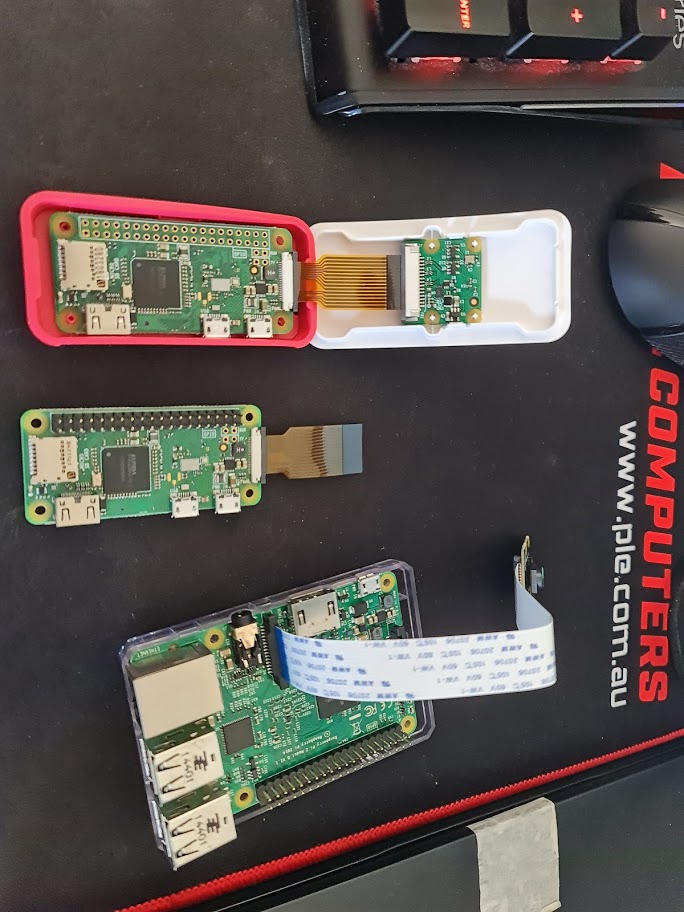
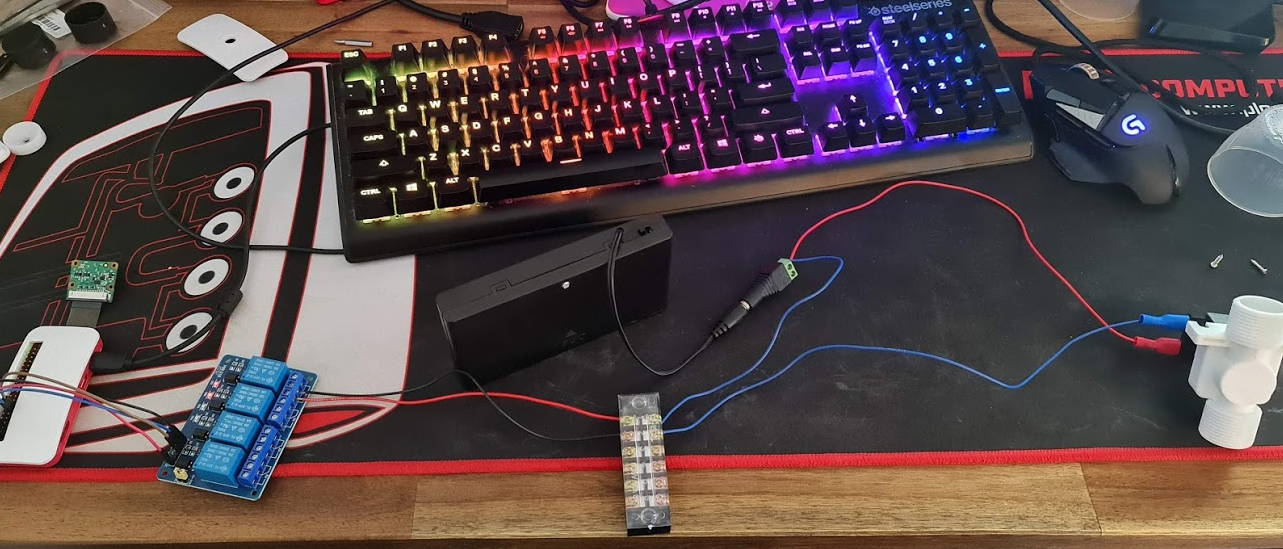
The package of miscellaneous parts arrived and I got to work stripping some wires, putting some crimp terminals and spades on the end of wires from some surplus auto equipment I had lying around. I've also connected some cameras up to get started with some kind of ML. My desk looked like the below for a few days.
I'm mildly excited at this point - having had to fight Python and dependency issues, I've managed to get a small script to turn on and off some pins working on the dreadfully slow Raspberry Pi Zero. I mean, who knew that having Python 2.7 and 3.5 on the same distribution would cause as many issues (do I use pip or pip3, python or python3?). There's a certain sense of achievement you get when you manage to control a physical object. Perhaps it's the sound of a relay clicking and a solenoid *thump* that makes all the difference.
from gpiozero import LED
from time import sleep

hose = LED(17)

while True:
    hose.on()
    sleep(1000)
    hose.off()
    sleep(1000)
The above script won't win any prizes for creativeness by any means, but that's really how simple it is to start turning stuff on and off. I'm not exactly a fan of Python and I dislike YAML for similar reasons. When you get used to C-style syntax, the mark up makes it pretty easy to place code the way you want to see it. It's fair to say I've developed my own preferred styles for laying out code so moving to a different language that also removes some of these "features" can feel unpleasant. But this is where I think I made a mistake.
I figured that I've been working with Typescript for around five years now, surely these examples are available in Node.js. Of course, there absolutely were examples - there just weren't very many of them compared to Python. When you start going down the Machine Learning path on the other hand, things get a lot murkier and in some cases you end up with Javascript wrappers for Python scripts of which are wrappers for C libraries themselves. This doesn't strike me as robust enough to have such a chain of possible failure points. To add to it all, the Raspberry Pi Zero is also only Armv6 capable - Node.js stopped supporting this architecture sometime in 2019. But I know how to write a basic express app in Node.js so I gave it a good go.
Before I knew it, I had imported onoff, lodash, fs, lowdb, fs, cors, nodemon and started scaffolding some API endpoints. After all, any logic I have that detects images from a camera will need to pass detections to an API method - this would allow some abstraction to take place. With Docker installed on the Raspberry Pi Zero, I'd eventually build an image based on the balenalib/raspberry-pi-node image.
NB: Which by the way, if you're trying to build containers to run NodeJS on Raspberry Pi Zero hardware, the following snippet will be super useful. There was a lot of trial and error to get this exact package and image for the job...
FROM balenalib/raspberry-pi-node AS base
RUN install_packages make gcc build-essential python3 influxdb
A word of warning, it's not a great idea to build these images on the Raspberry Pi Zero directly unless your idea of fun is to spend 30 minutes waiting for all the dependencies to compile and install. If you don't get your multi-stage builds right, this becomes a lot more fun when you have an error further down in your Dockerfile. As I learned through building these images, they are multi-platform by default so building them on a far superior computer and pushing them to a shared private repository was a really good way to handle the compile time slowdown issue.
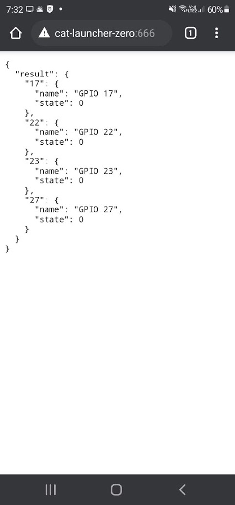
Suffice to say though, I managed to build something that would respond to commands like:-
- /gpio/{pin}/{state}/{timer?} - where pin = GPIO Pin number, state = on or off and timer = how long (0 = indefinitely).
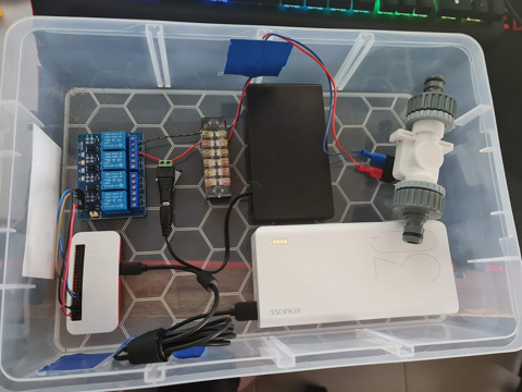
Pretty simple stuff. Or at least I thought it was. Things kind of worked - you need various levels of privilege escalation to get this thing working but perhaps the biggest issue was that I'd just spent a lot of time coding something that really didn't need to be this complicated. But it did work, so I put the image into a Docker Compose script, set to always run and loaded it in a box.
Machine Learning
Before, I mentioned Python having a good set of resources available especially when it comes to tinkering about on a Raspberry Pi. Having powered up the Raspberry Pi 2 I had lying around, I connected the camera to it and ran a few example Python scripts on it to see what kind of framerate you could expect - having not done much with Object Detection beyond a proof of concept project at work with Amazon Rekognition.
The first example I downloaded revealed some success - it wasn't overly fast, maybe 3-4 FPS but it could pick up some things like monitors, chairs and teddy bears. I wish I had kept a photo of this one.
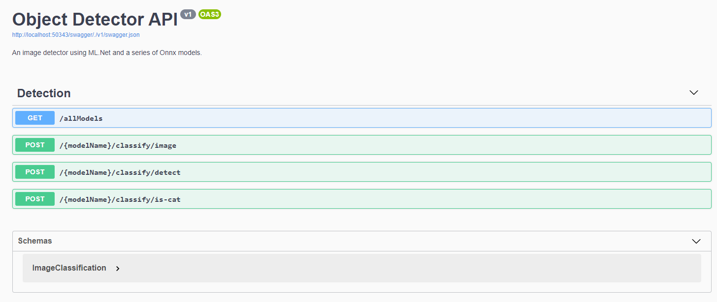
All well and good if I want to use this particular library and run the application on the Pi itself, but it definitely wasn't great at detecting cats nor was it very fast at doing so. If I'm going to start writing some serious logic - it's time to do some learning. Microsoft had recently announced ML.Net having a feature update and I figured instead of learning more Python, I could put some C# skills to use. I stumbled across some examples on getting TinyYOLO v3 running on ML.Net using Onnx. There's a lot of material to cover here, perhaps for another blog post. But if you're starting out in Machine Learning and think reading this one example is going to solve all of your Machine Learning queries, you'd be absolutely wrong.
When I started implementing pipelines, using Neutron to work out how to invoke the model and learning about how to reduce image quality to speed up image detection - it becomes overwhelming very quick, and most of your object detection labels and the way scores are calculated changes dramatically. Different settings start to throw out bounding boxes and even what's actually being detected. None-the-less, I'm only interested in "Cats" and "not Cats" - so I figured this should be relatively straightforward. With my API in place and several algorithms, it's time to test.
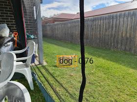
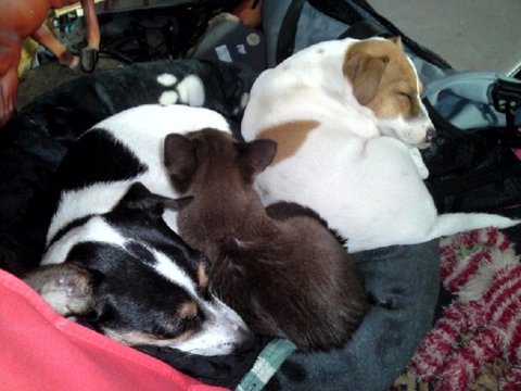
With so much excitement, I begin uploading some images. By about the fourth image, I was immediately excited that the bounding box is perfectly around the dog, and it detected a dog. That percentage could have been a little bit higher, but who cares - it detected the right thing!
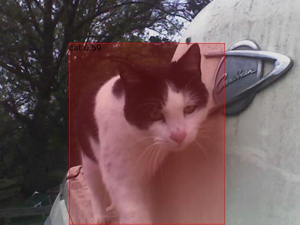
Some more pictures in, and we finally get to a pretty obvious cat from some Aiptek camera back in the day (remember those guys?). The percentage wasn't exactly super high, but you can only see two legs. Maybe that's why ;)
Alright - time to give it something obvious - two dogs and a cat. What do we get? - bzzt. Nothing.
Suffice to say, I went through a lot of different kinds of models to try and determine the best one for the job. Some were slow, some were fast, nearly all of them were only producing < 1 frame per second on non-GPU accelerated hardware. I even had a go at general image classification - and despite only having two kinds of things I was looking for, most algorithms there were basically treating things as "Cat" or "Not Cat" - rather than a whole list of possible outcomes. But - I did have some success so I would proceed to bundling this up in an image with all available models ready for testing.
The RTSP debacle...
It was clear early on that the Raspberry Pi's camera was pretty ordinary. I had however purchased a Ubiquiti Camera - the Bullet G4 and mounted it to the front of house. There's a few cool things that this particular camera supports - RTSP is probably the most important as well as some Motion Detection that I can hook into. All I needed was an RTSP library to get images from the stream (short of writing my own RTSP interpreter - surely I'm not the only person in the world consuming this feed), and I'd pass it onto the detection API before deciding whether I wanted to turn the relay on (and for how long).
Well - this turned out to be an even bigger hurdle than the Machine Learning itself. After traversing through Github and Nuget for libraries, it was pretty clear that RTSP feeds can be vastly different, and most were designed for particular cameras or use cases. In particular, the Eufy camera I had before kept breaking most C# libraries I was trying to use, except for Emgu.CV.
Turns out, this Machine Learning library does have a fully baked RTSP reader and it works fine if you're running everything on Windows. I was not - my servers are mostly Linux and anything Windows are my desktop PCs which are used for a lot of other things (and despite having Solar Panels on the roof for daytime, I don't want to be chewing up that much electricity for the one or two times a night a cat may be detected). Despite following build instructions for Ubuntu, I could never get the library working without throwing many dependency errors.
The Emgu.CV library requires a few dependencies:-
- Emgu.CV
- Emgu.CV.runtime.windows
- Emgu.CV.UI
With these installed, connecting to the RTSP stream is fairly trivial. You create a VideoCapture object, subscribe to the ImageGrabbed event and start the feed. You can hook into various error methods to attempt a retry in case of disconnect but for the sake of brevity in the code below, I've kept it super simple as it's useful if you ever need this, at least in a Windows environment.
var capture = new VideoCapture("rtsp://...");
capture.ImageGrabbed += ImageGrabbedHandler;
capture.Start();
void ImageGrabbedHandler(object sender, System.EventArgs e)
{
var frame = new Mat();
var captureRetrieved = Capture.Retrieve(frame);
if (captureRetrieved)
{
var frameImage = frame.ToImage<Bgr, byte>();
var bitmapImage = frameImage.ToBitmap();
// throw this bitmap whereever it needs to go
}
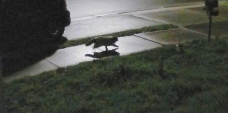
}Unfortunately, this is where the Cat Launcher venture ends. Having installed the camera and attempted some image detections, it's clear the algorithms aren't quite working. In some cases, it was detecting the local neighbourhood kids as 'Cats' from time to time, and 'Cats' as 'Dogs' and various other anomalies. That's not to say all of this is wasted, I'll definitely be picking it up again. But as I headed into Autumn and Winter, the cats don't tend to spend too much time digging up the lawn. Or perhaps the Jack Russell that was staying with us may have helped keep some of the cats away. In any case, until these images can correctly identify a Cat, this project is on hold.
In the meantime, and for my next post - a new project cropped up in May to automate a gardening system. Having installed a bunch of Planter Boxes to grow some veggies, the same kind of system at least without the Machine Learning component is required. So I've pivoted to building an automated gardening system in the meantime. Stay tuned for Part 2!
Building a Raspberry Pi mini rack - Part 1
Earlier this year, I managed to amass a table top full of electronics. Arduino's, Raspberry Pi's, Breadboards and components - you name it, it was covering my desk. Most of that is now packed in drawers thanks to the 3D Printing workbench I built last weekend. With a growing number of projects requiring GPIOs or just brushing up on my Kubernetes skills, I need a way to logically organise my growing collection of Raspberry Pi 4's such that they are all usable and clustered for some upcoming projects.
The obvious choice was to build a mini rack that can stack neatly on the table while doing some development work. Each Raspberry Pi would need some way to quickly identify what's going on (via an OLED screen) and ideally a few LED lights for some general purpose identification work. This rack would need it's own power and networking, ideally with the capability to add a Mobile Internet (USB) or Wireless capability for any portable or outdoor use. With this in mind, the part list is below.
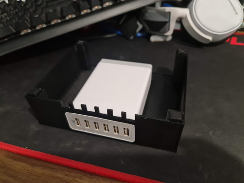
- 1 x Anker 60W USB Charger - This device looks great on paper and should comfortably run 3 x Raspberry Pi 4's with it's 15W draw at full load.
- 3 x Raspberry Pi 4's - The brains of the operation - while there are plenty of limits on the cheaper Pico's and Zero's, these don't tend to have restrictions so you can find them around fairly easily. I've opted for 8GB ones to add extra room for database containers.
- 1 x TP-Link AC750 - This ended up a difficult choice. The location of the Ethernet Port and Switch sold me on this one, the USB cable for Mobile Internet can be accessed on the side so this is a bit easier to get to than some of the other more capable GL.Net devices. The lack of an extra Ethernet port for WAN is a downer, but given it's only to provide internet connectivity to the cluster, the Wireless capability will have to do. It's also compatible with DDWRT so if I find myself stuck, there are a few hacks that might help this out.
- 1 x Ubiquiti Mini Switch - This USB-C powered mini switch has enough ports to connect the 3 x Raspberry Pi's, the Router and one spare for plugging a laptop into (or perhaps another network if the TP Link device is unreliable on Wireless.
With the parts sorted, it's time to determine what kind of rack to build. There are plenty of kits around for clusters - GeeekPi Raspberry Pi Cluster Case comes up a lot. On one hand, it looks to be sturdy and portable for the Raspberry Pi's themselves but the switch, router and power pack would need some work. There are many other similar styles all centred around the brass spacers and Perspex cut-outs but they're really just bigger with more fans and LEDs in the way.
Down the reddit rabbit hole, and there are a number of different 3D print options. The Ubiquiti Mini Rack was certainly appealing from a design and function perspective especially for odd-shaped components. As I'm looking at mounting some Raspberry Pi's though, I'd need to sketch up something modular to fit. I started mocking up a few designs in SketchUp 2017. Nothing too fancy at this stage - just something that would enclose each device with some cable management and the ability to stack them as I go. Having come up with one design for the Power Adapter, things were looking promising.
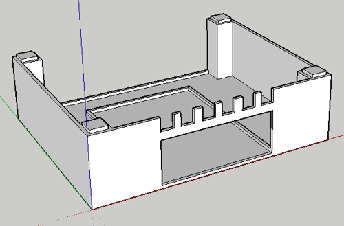
I wasn't too sure about having the USB power connectors go back through the case, as you might on a proper rack - but it would at least be sturdy. Other subsequent modules would match dimensions and become smaller or taller as required. Unfortunately, with 6 modules the height would be around 24cm. That's getting pretty tall - certainly taller than my PC case for sure. A few prints later and you can see that it's starting to take shape.
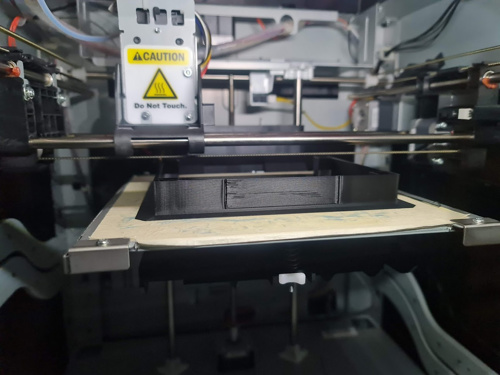
The first problem: the printing process was not great. These are some early prints after getting back into 3D Printing and many mistakes were made. I had assumed, for some reason, that I loaded the ABS Black spool in but it was PLA - I wouldn't find this out for some prints in. I had set the heat setting far too high for PLA - and just slightly low for ABS. The end result was that the molten plastic effectively scorched the printing tape underneath and caused a number of problems with the printing tape being embedded in the print itself. As I printed more, the quality seemed to get worse and the temperature of the garage certainly played a part in whether the first layer would stick to the tape.
Google and YouTube were fairly unhelpful - not because the content was wrong, but what I assumed to problem to be was wrong. I had followed advice to try Blue Painters Tape for adhesion, and this worked a little better. When I finally discovered that I had loaded the wrong spool in and I set the right temperature for PLA instead, it was far easier to replace the tape and so I continued a while with it.
I had only bought the one roll of PLA and further research would suggest and prove to be a far easier material to print with. But I'd bought several roles of ABS and needed to sort that one out. With some trial and error, I eventually settled on a Glass Square (200mm x 200m) with some Hair Spray to keep the ABS plastic down, and some Aluminium Foil inside the printer to help keep the heat in during printing (this had more of an impact than I thought it would - being in a Garage, it gets very cold in Victoria!). With some manual calibration of the Printer Bed, this turned out to be the best solution for both PLA and ABS. No more tape, super easy process to follow. If there was one thing I wish I knew before starting these prints again, is what 'bad' looks like.
There were a few other prints that were frankly rubbish. The design looked horrible and function definitely wasn't as good as it could be. So I continued browsing through Reddit and Thingiverse for more ideas. I saw a recent post about the Monty rack. This thing looks absolutely amazing albeit overbuilt for my purposes - but the concept is spot on. The case uses slotted extruded aluminium for the supports and 3D Printed rackmount inserts to mount everything in place. Prices in Australia for aluminium is not cheap though and frankly at the price just for the supports - I could certainly build something like this in a more visually attractive way, such as a wall mounted cluster.
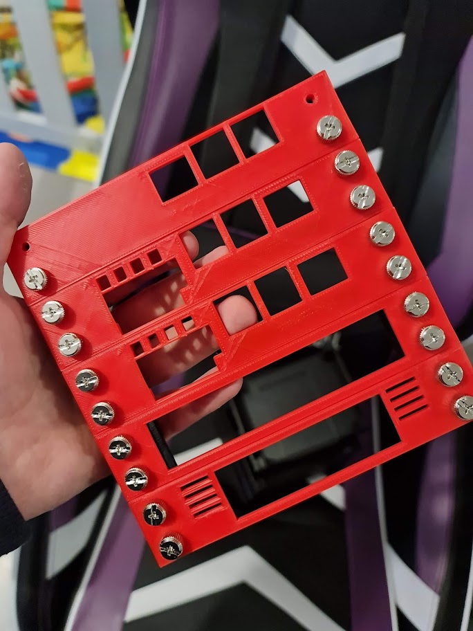
I ultimately decided not to do that (although it would have looked pretty cool with some water cooling and cables laid out on a board), and instead look at 3D Printing some supports. I would design a 2cm x 2cm design, with a trapezoid cut out to help give the screws themselves a little more plastic to help hold each face plate in place. Each 'RU' would effectively be 3cm high, and 15cm wide (11cm usable space, given the 2cm each side). The power supply will be mounted at the back, inside the rack 'square' and as such would create a nice little cube - around 15cmx16cm accounting for legs and a top (20cm if I decide to add handles).
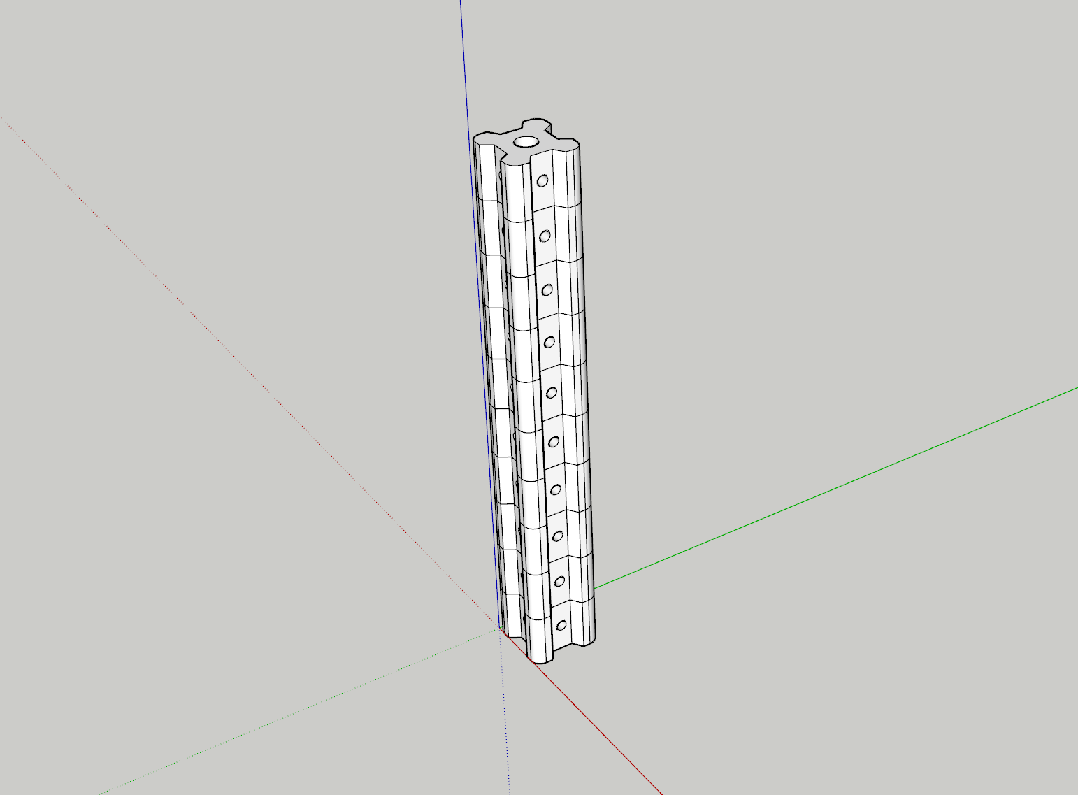
The holes are small enough to enable some self-tapping from some leftover M3 Thumb Screws I have from an old PC Repair kit to hold the face plates in place and each end will enable some standoffs to be glued in place to hold the top and bottom 'lids' in place. I chose Black for the Aluminium extrusions, Grey for the trays to hold components in place and Red for the face plates. The design would be somewhat reminiscent of 80's style electronics.
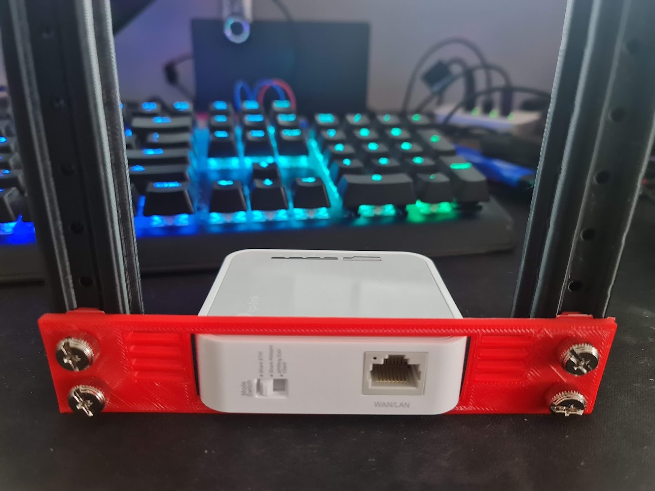
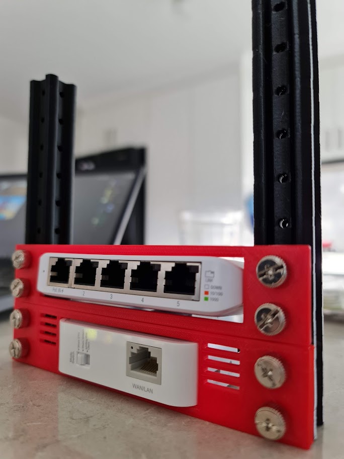
Ok - this thing looks about 1,000x better than the previous attempt and far better than I thought it would look. The holes are the right size for those M3 screws to grip without being overly troublesome (although if I were to do this all over again, I'd probably make the holes around 0.5mm smaller again) and the sizing for the first component is spot on. I'd just need to print a tray for this to sit in, some other faceplates and the other supports. If the Raspberry Pi now fits in the rack, along with the LED Lights / Buttons and OLED screen, we should be onto a winner.
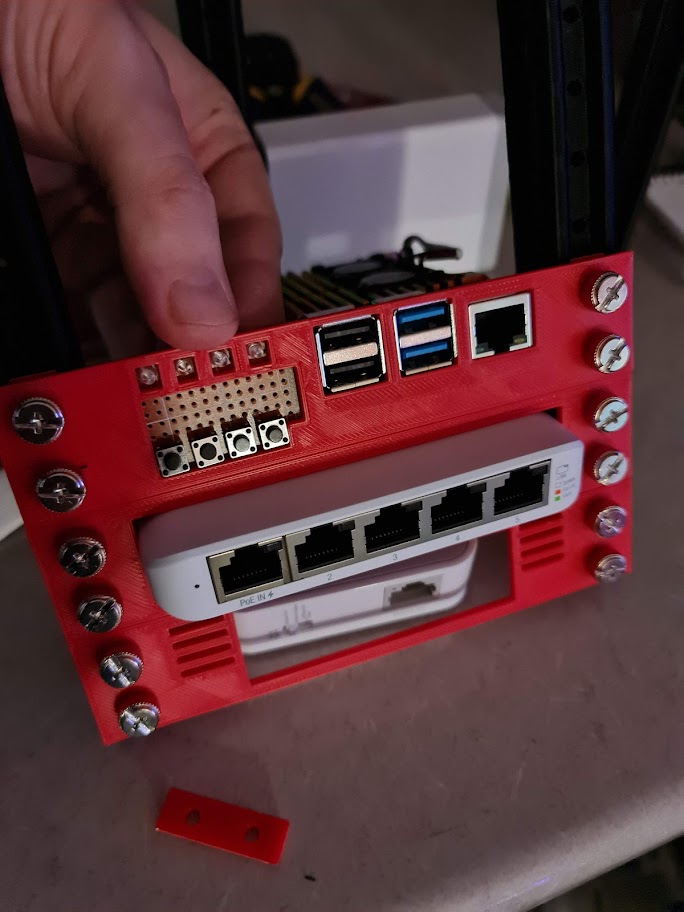
This Raspberry Pi faceplate probably took the most amount of time to get right - aligning the USB and Ethernet ports. I needed enough room to place the 4 x 3mm LEDs, 4 x Push Buttons and enough room for a 128x32 OLED Screen. The idea being that I can see what's running on each Raspberry Pi without necessarily logging in to see what's going on. If I need to reboot them, I can do it from the controller. The lights will help build and diagnose some GPIO projects and also enable the remainder of the rack to run a series of ARM-compatible containers. I would use a consistent approach for cooling via an Armour shell - if these things are running databases and Kubernetes, as well as powering a potential light show at the end of the year, then they're going to produce a fair bit of heat from each CPU.
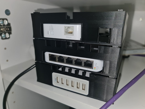
This leads up to the end of May when I thought I might only require a Raspberry Pi 2 as the Kubernetes master node. This has changed in design since then, but to give you an idea on what a full stack would look like (and when I noticed I didn't have an extra two thumb screws), I've placed the photo below.
At this stage, I'm pretty happy with the progress but still have a little bit more to do. For starters, I'll need to wire up a screen, buttons and do some programming before finalising the PCB for the slot. Secondly, I'll need to print all supports and the cover for top and bottom.
But that's where this post will end. Until next time!